Firefly with Vicon Tutorial
Pre-setup
- Simulation: successfull test of your own controller on GAZEBO
- Packages installed
- Firefly OBC
- asctec_mav_framework: framework for data aquisition and position control to be used with the highlevel (HL) processor of Ascending Technologies helicopters
- MSF: Modular framework for multi sensor fusion based on an Extended Kalman Filter
- Controller: in this tutorial, the gain-scheduling controller will be tested
- Remote Computer
- VRPN Client: connects to the Vicon server through the Virtual Reality Peripheral Network; provides position, orientation, velocity and angular velocity.
- Firefly OBC
- Power on
- Asus router (WiFi network mrasl)
- Netgear switch (2 TP-Link Wireless Access Points)
- 2 Trendnet switches (Vicon cameras)
- Firefly's FCU (flight control unit) with an ASCTEC battery fully charged (5000 mAh, 11.1V)
- Firefly's On-Board Computer (OBC)
- Vicon setup: see our Vicon page for more detail.
Network Setup
Remote monitoring and control the Firefly from a distance computer. In this tutorial, the desktop L5816-18 and the object firefly_blue are used.
IP address: the remote computer and the firefly have to be connected to the same network (MRASL). The firefly_blue IP is 192.168.1.12. For this tutorial assume that the remote computer IP is 192.168.1.4. You can check your IP address by typing ifconfig in a terminal.
Remote monitoring and control of the Firefly from a distance computer
- Check the connectivity between the remote computer and the
firefly_blueby running the following command in a remote computer terminal$ ping 192.168.1.12 To log into the Firefly's OBC we use the following commands
$ ssh asctec@192.168.1.12This command will open a ssh channel to the
firefly_blue(default password isasctec). If you are using the desktop L5816-18, you can also running the permanent alias$ connect_firefly_blue.We will use the
firefly_blueas the ROS master, by setting the ROS_MASTER_URI and ROS_IP variables to the drone's IP. To change the variables we use the following commands in the remote computer terminal$ export ROS_MASTER_URI=http://192.168.1.12:11311 $ export ROS_IP=192.168.1.4If you are using the desktop L5816-18, you can also running the permanent alias
$ master_firefly_blue
Before your fly
Setting up the ROS environment: don't forget to run $ source devel/setup.bash in each terminal before continue with the following subsections. If you are using the the firefly_blue and the desktop L5816-18, you can also running the permanent alias $ gotien.
Firefly's OBC
- If you want to implement your own controller, you should list and kill all default nodes on OBC by running the following commands
$ rosnode list $ rosnode kill /AsctecProc $ rosnode kill /AutoPilot - Running
/fcu,/mv_26805107nodes (Asctec Framework HL interface) and/pose_sensornode (MSF, private name)$ roslaunch asc_hl_interface fcu.launch $ roslaunch msf_updates viconpos_sensor.launch
Remote Computer
- Running the
/firefly_blue/vrpn_clientnode
This launch file is a copy of the original$ roslaunch ros_vrpn_client mrasl_vicon.launchasl_vicon.launch, using for thefirefly_blueobject and the Vicon server IP 192.168.1.200<arg name="object_name" default="firefly_blue" /> <node ns="$(arg object_name)" name="vrpn_client" type="ros_vrpn_client" pkg="ros_vrpn_client" output="screen"> <param name="vrpn_server_ip" value="192.168.1.200" />
After running these launch files, the /pose_sensor node may show this message (OBC terminal): Pose measurement throttling is on, dropping messagesto be below 50.000000 Hz.
Init the filter
Open a rqt GUI in a remote computer terminal by typing $ rqt
Verify running nodes
- Menu
Plugins/Topics/Topic Monitor: check filter input/output data- Filter input from Vicon: topic
/firefly_blue/vrpn_client/raw_transform, 250Hz - Filter input from Firefly: topic
/fcu/imu, 100Hz - Filter output:
msf_core/poseormsf_core/odometry, 100Hz
- Filter input from Vicon: topic
- Menu
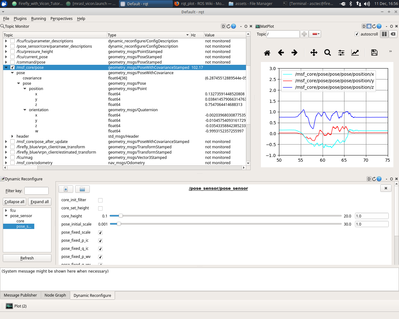
Plugins/Visualization/Plot: plot the position, velocity, ... - Menu
Plugins/Introspection/Node Graph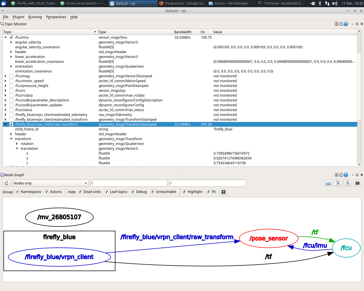
Init the filter
- Menu
Plugins/Configuration/Dynamic Reconfigurefcu/fcu: chosePOSCTRL_OFFforposition_controlandSTATE_EST_OFFforstate_estimationpose_sensor/pose_sensor: click oncore_init_filter
Move the drone and check
After init the filter, the /pose_sensor node has to show a message (OBC terminal) as: initial measurement pos:[ 0.158259 0.0267092 0.754158] orientation: [0.998, 0.00129, 0.025, 0.0552] and some other messages.
Running the demos
Before running the controller
- RVIZ and RQT
- Check our Safety page
- Remote control
- Start the motors
Running the controller
- Running the controller node by typing the following command in a Firefly's OBC terminal
$ source devel/setup.bash $ roslaunch gstf_control lqr_controller.launch - Menu
Plugins/Introspection/Node Graph: check node - Check the data before active the controller
Topic
/firefly/command/motor_speed/angular_velocitiesand/firefly/command/motor_speed/normalizedshould have to be0.0for all components. - Active the controller: change the remote control to autopilot
Send the reference
menu Plugins/Topics/Message Publisher
- Add the topic
/firefly/command/poseby using the button+ - Change the value of
pose/position/zto0.5 - Check the box to publish
Verify the result
menu Plugins/Topics/Topic Monitor
- Command: topic
/firefly/command/motor_speed/angular_velocitiesand/firefly/command/motor_speed/normalized - Output: