How to Calibrate the Vicon Setup
Always recalibrate the Vicon every day before starting to work.
This guide is currently being validated. Please contact Olivier Gougeon for comments or suggestions to improve it.
Before You Start
The before-you-start-checklist:
- Is the floor well covered? (Undesired reflecting surfaces are your #1 enemy while using the Vicon system!)
- Are all the objects in the flight area placed in their experimental configuration? (Mats, tiles, nets, etc.)
- Am I in a good mood today? (If not, you might want to consider NOT doing any experimental tests today...)
If you answered YES to all the questions above, you are now free to proceed to the next step.
[Partially Optional] Using the Vicon Control Mobile App
N.B. Some of the steps provided in this section are specific to the usage of the Vicon Control mobile app and are therefore optional. All of the other steps must be done to be able to use the Vicon system.
The Vicon Control mobile app is available for iOS or Android devices. You may dowload it visiting the App Store or Google Play. It allows you do to different things such as playing with the camera and calibration settings. It is mostly useful for the calibration process as it allows you to view directly on your device (phone or tablet) and in real-time the advancement of the calibration process underway.
Follow these steps to use the Vicon Control mobile app during the calibration procedure:
[Optional]
Connect the black Asus router to the school's network (use an ethernet cable and link the blue port from the Asus router to the school's acess point located on the wall next to the Vicon computer)==> NOW PROHIBITED by the Service Informatique Polymtl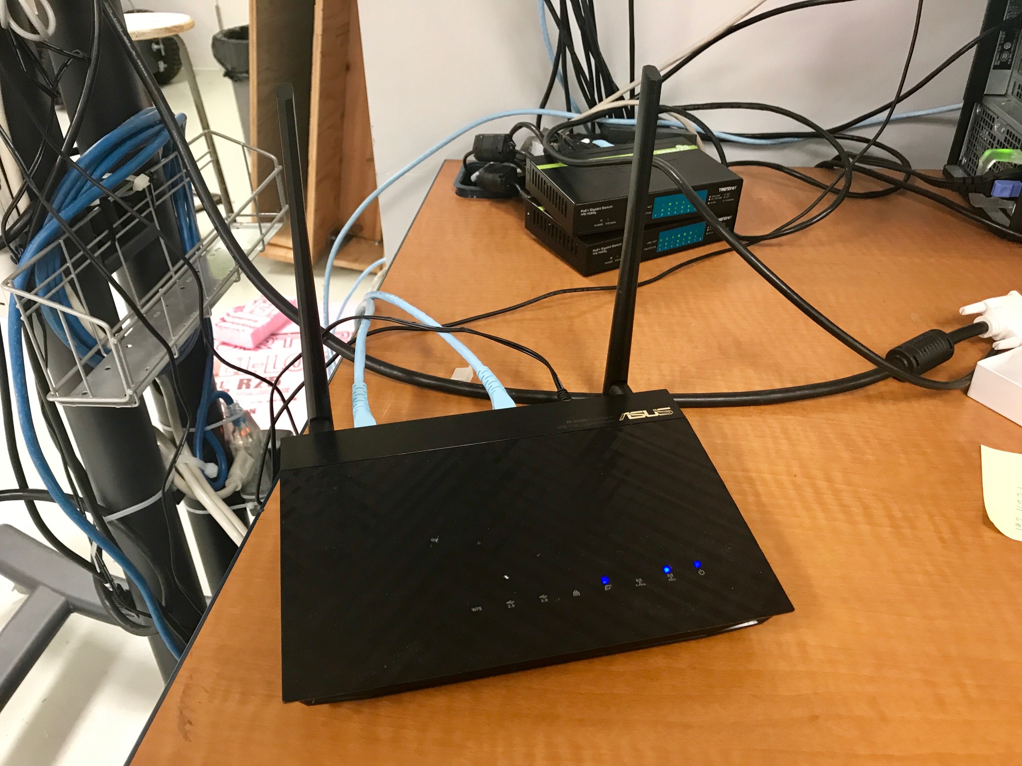
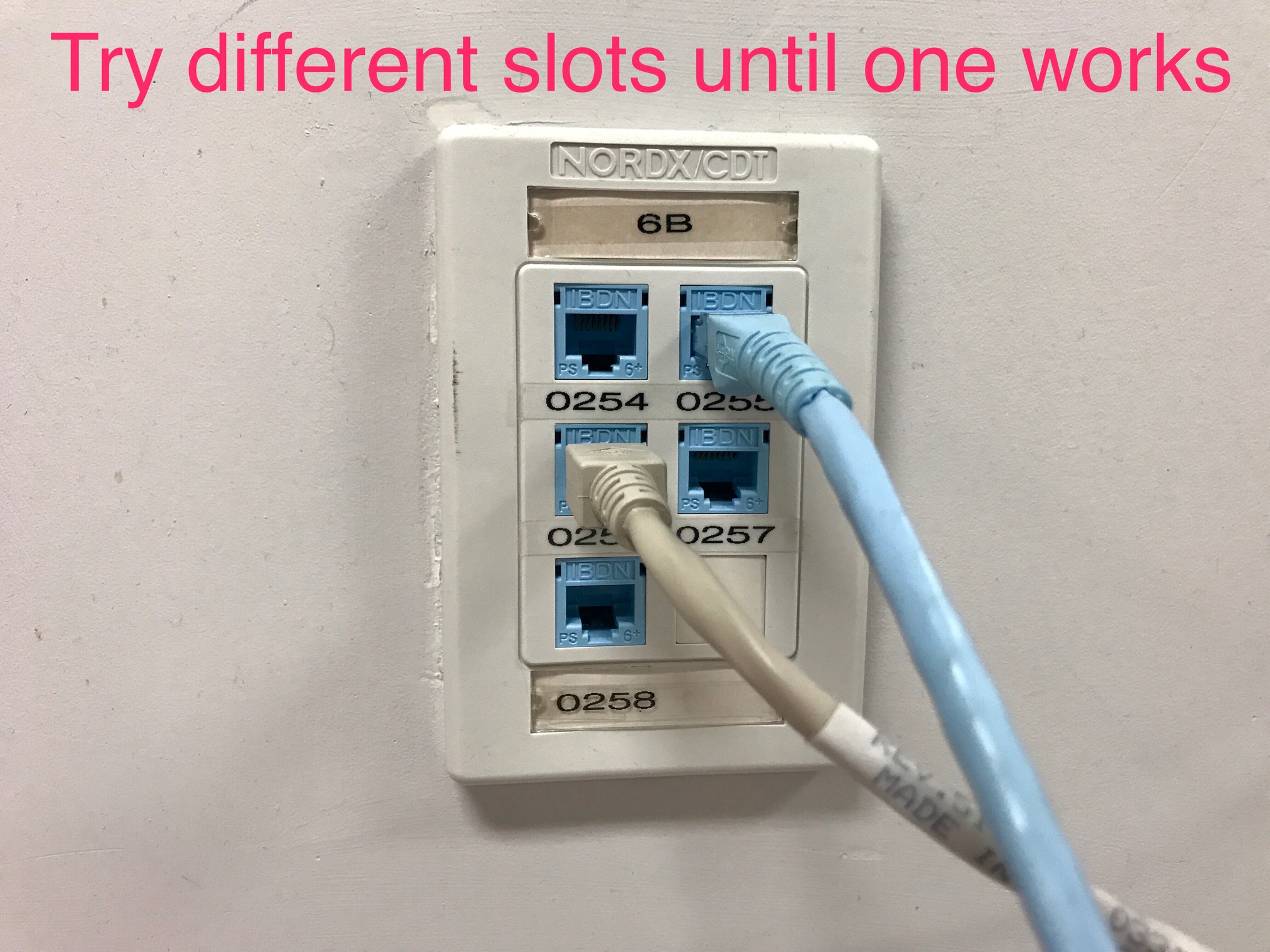 N.B. The
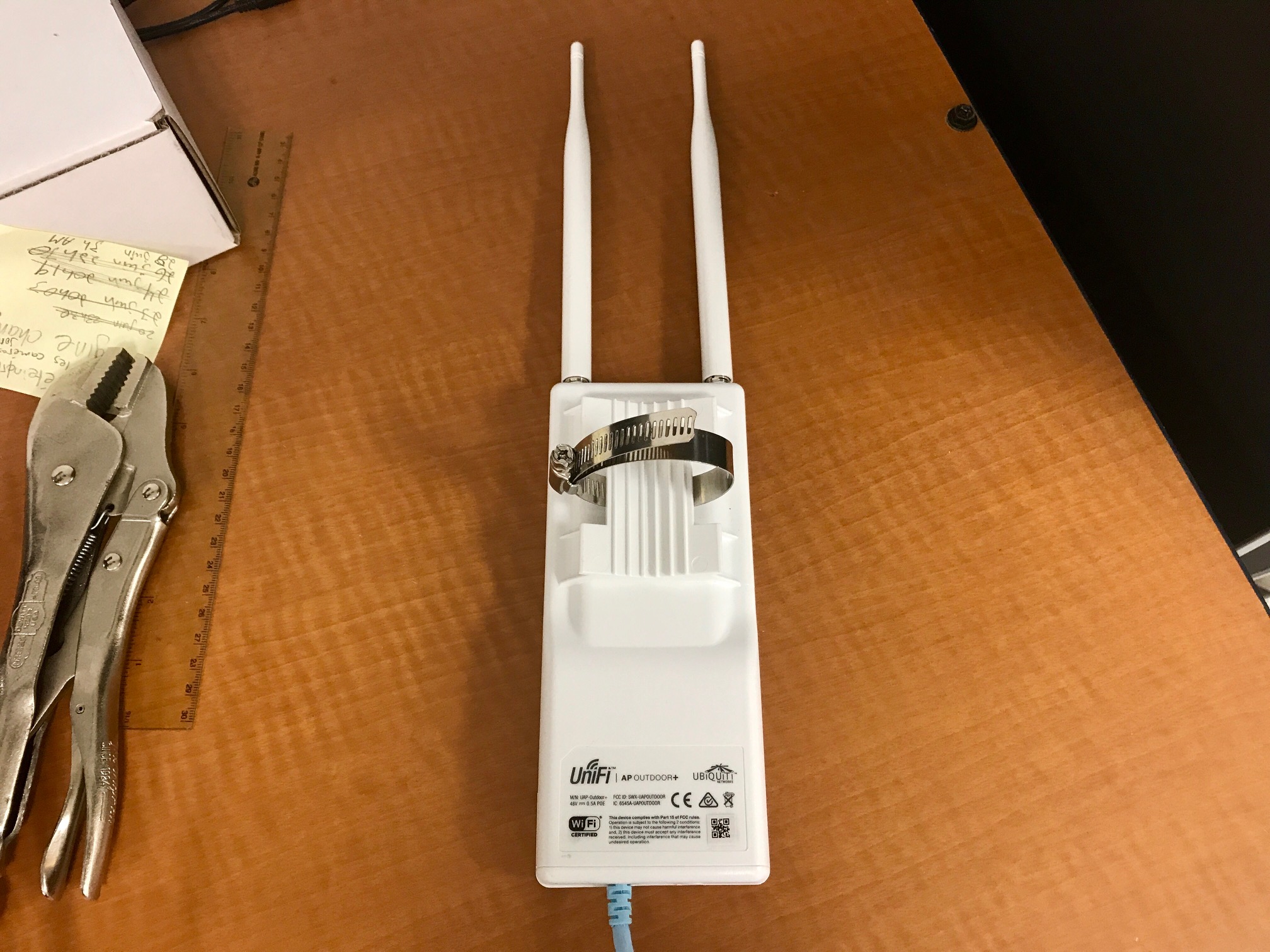
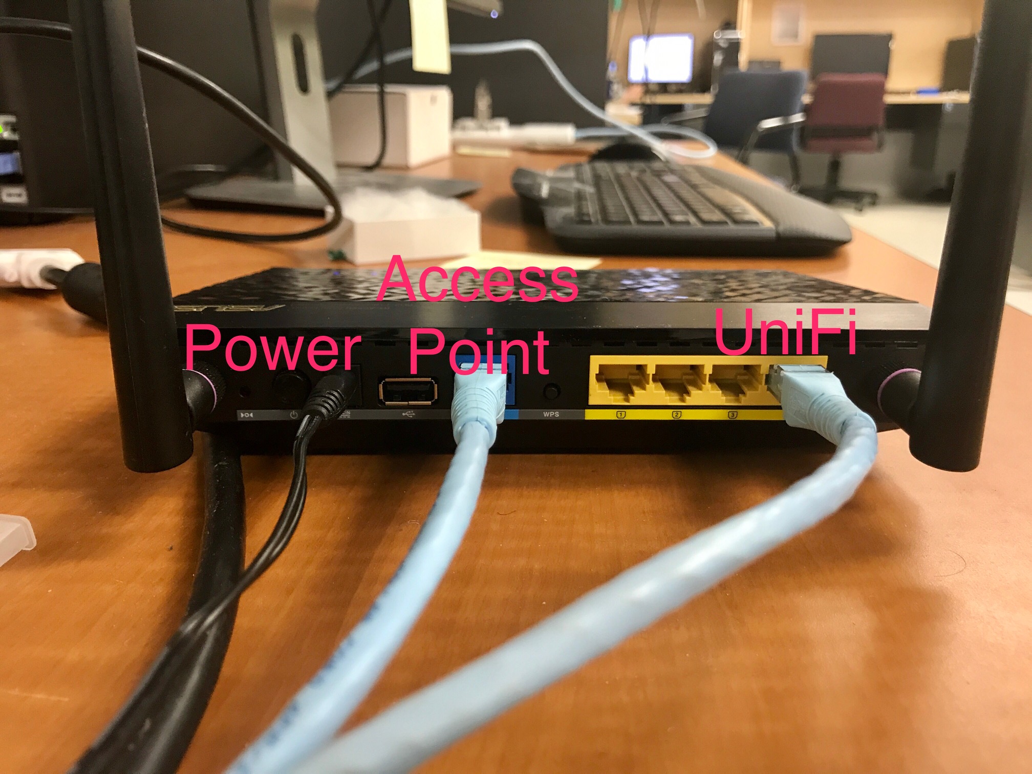
 0257port is not activated. Please refer to the list of activated ports displayed on the post board located at the entrance of the lab.[Optional] Connect the white UniFi double antenna to the Asus router (plug the blue ethernet cable from the antenna to one of the available yellow ethernet slots of the Asus router)
[Optional] Power on the Asus router (the switch is located in the back of the router)
[Optional] The WiFi network mrasl should now be discoverable on your mobile device
[Optional] Login to the mrasl WiFi network using the password that is written on the post-it located on the Asus router
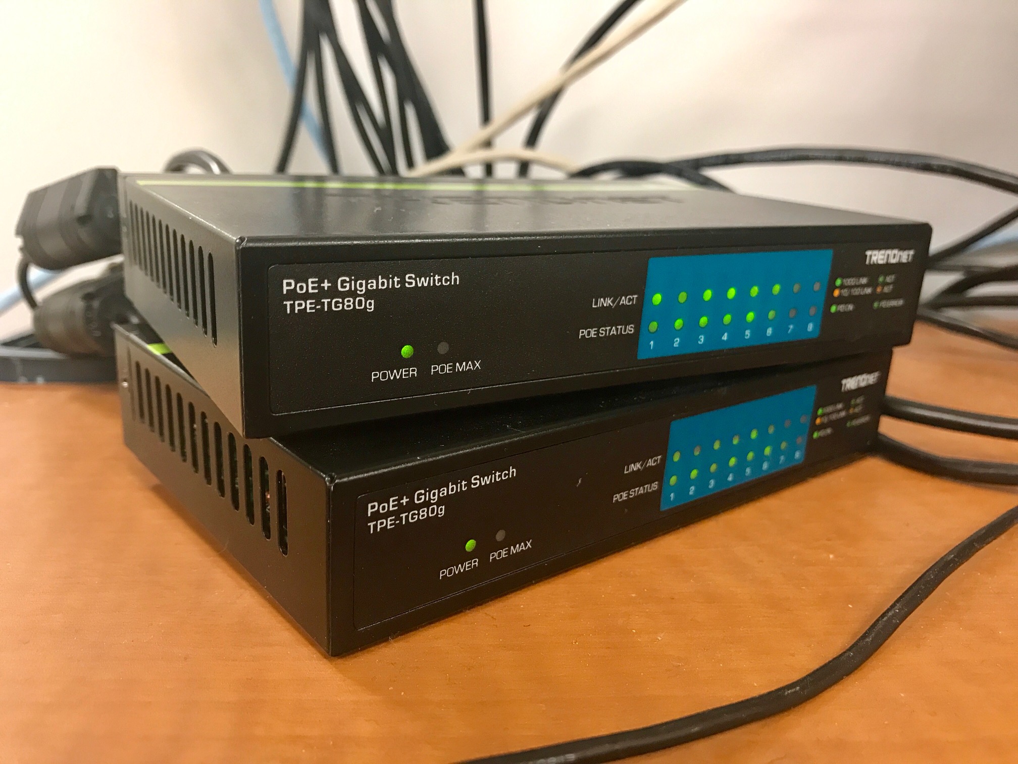
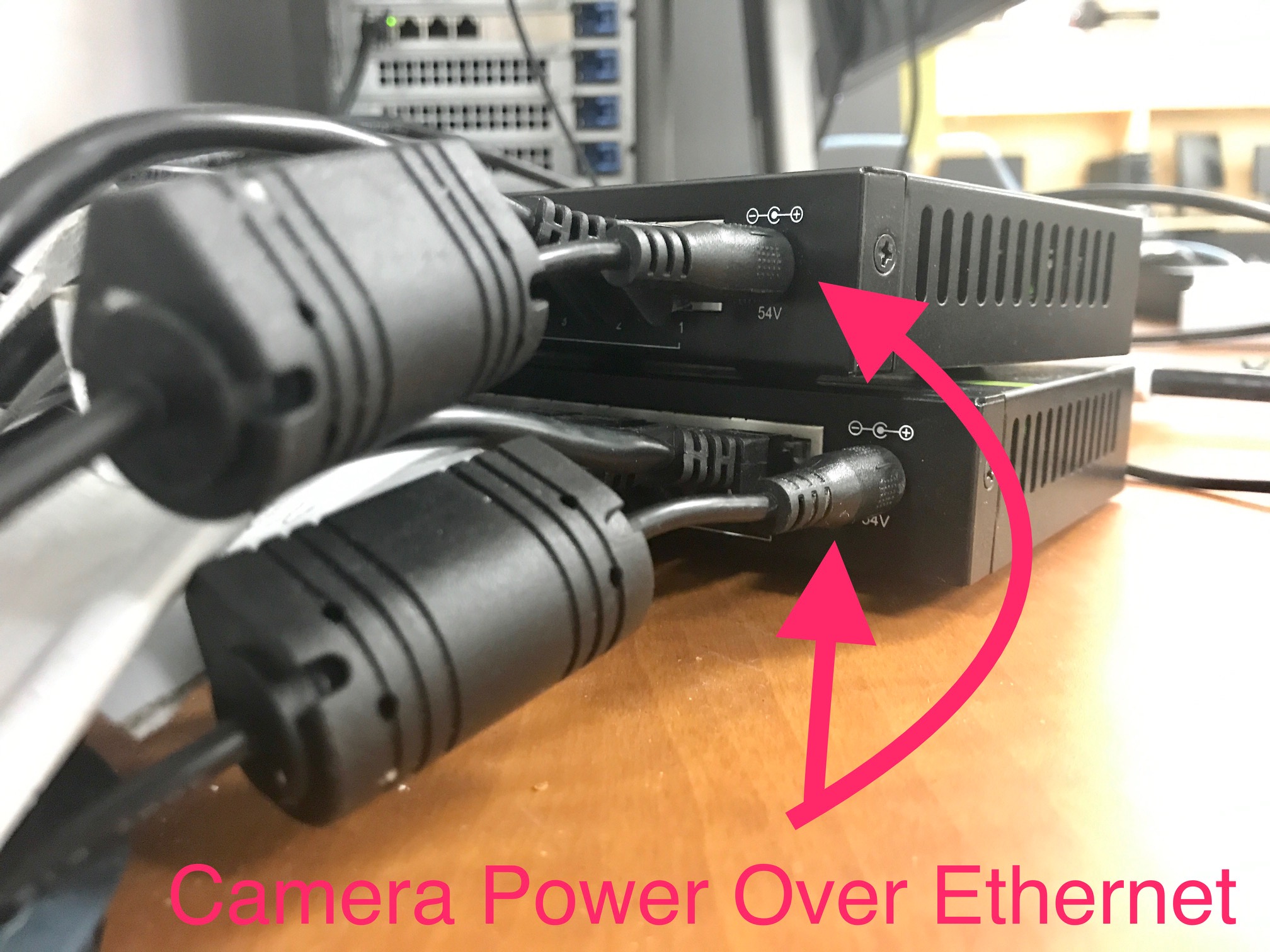
Power on the Vicon switches (connect the two power supply cables)
Power on the Vicon PC
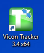
Launch the Vicon Tracker application (the green shortcut is situated on the desktop)
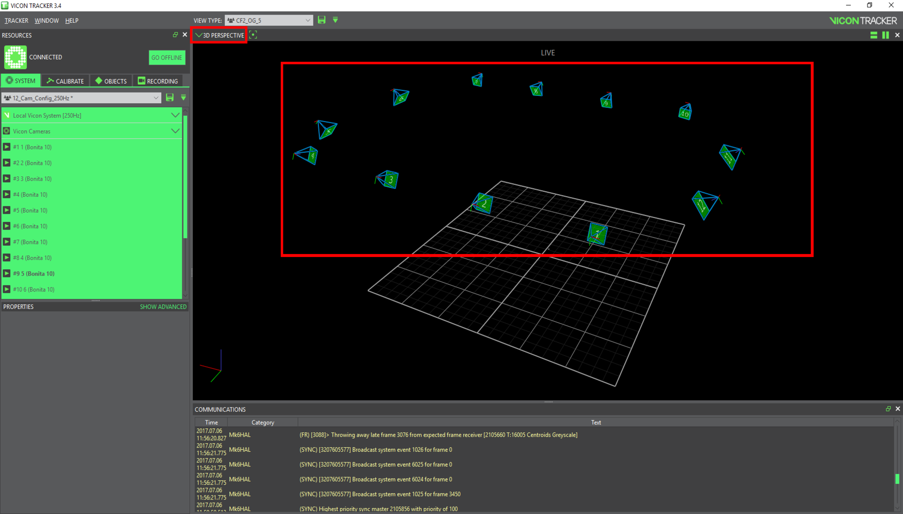
Choose the 3D Perspective view in the drop-down list
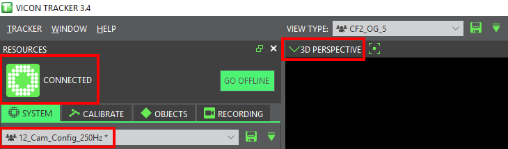
Make sure that all of the 12 cameras are green
[Optional] Open the Vicon Control app on your mobile device
[Optional] Select Connect Manually and enter the following info:
- Server IP: 132.207.24.6 (this is the Vicon's static IP address)
- Data Stream Port: 801
- Control Stream Port: 803
[Optional] Click on Connect
[Optional] A pop-up should come up on the Vicon PC
[Optional] Clock on Allow to authorize the new connection
[Optional] You are now ready to use the Vicon Control app to navigate through the different camera views (note that the Vicon system is also ready to be used)
Calibration Procedure
This section details the calibration procedure of the Vicon system. It is extremely important to calibrate the system every day before doing experimental tests to garantee a millimeter precision. The main reason is that the cameras are mounted on metallic rails that vibrate due to structural stress caused by all the ongoing activities in the university.
Follow these steps to calibrate the Vicon system (assuming all the previous steps have been completed):
In the Vicon Tracker application, using the drop-down list, navigate to and select:
SYSTEM > 12_Cam_Config_Cal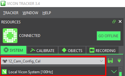
This is necessary to change the frequency from 250 Hz to 100 Hz in order to obtain better calibration performances.
Navigate to and select:
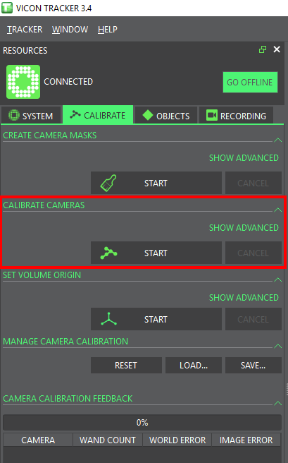
CALIBRATE > CREATE CAMERA MASKS > START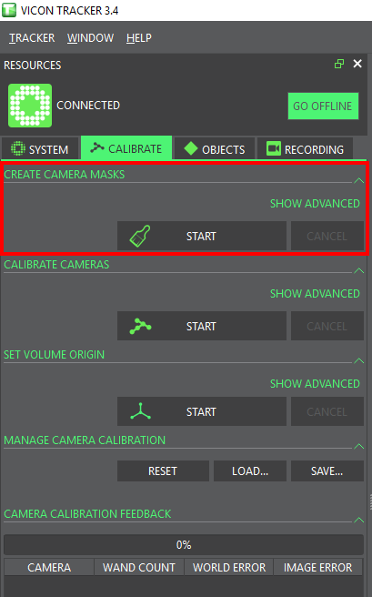
Wait a few seconds until all the reflective spots in the flight area become blue (they are initially white) and click on STOP N.B. All the blue spots do no longer belong to the 3D space being monitored by the Vicon system. Make sure that your vehicle will not operate in these dead areas.
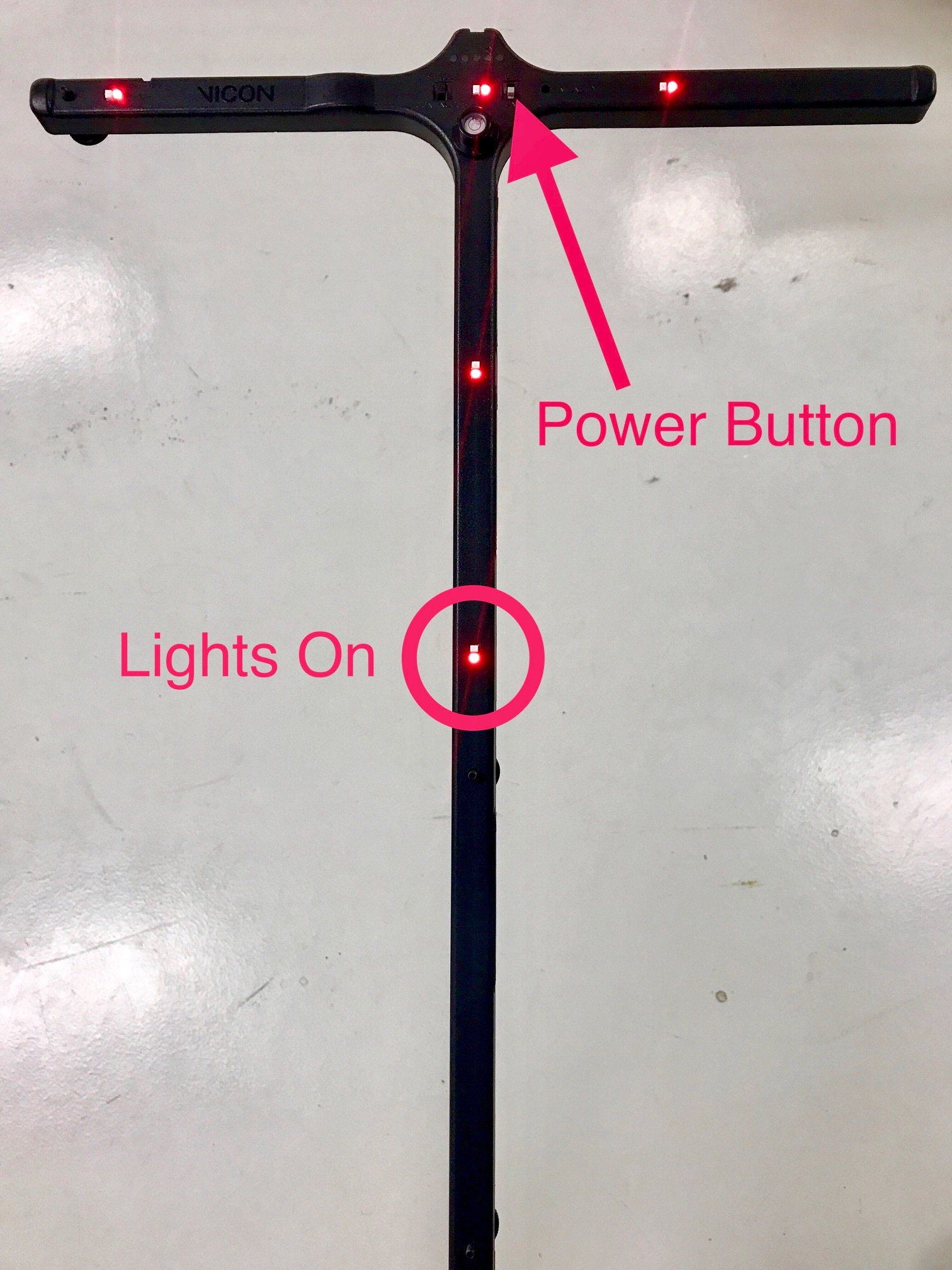
Power on the Active Wand and make sure that the 5 lights turn on (otherwise, you must charge the wand)
Navigate to and select:
CALIBRATE > CALIBRATE CAMERAS > START
`
Take the Active Wand and walk in the flight area doing arc-like motions with it over your head. You must pass infront of all the cameras. Make sure that the wand is always visible by at least two cameras.
Recommended: Use the Vicon Control app to visualize in real-time the calibration process.When every camera reaches 2000 wand counts, the calibration process automatically stops and the program goes into the final calculation process. If you look at the 3D Pespective camera view, you will now see that the orientation of the 3D flight area is all messed up. You must tell the Vicon system what is the new origin after each calibration process.
Place the Active Wand in the middle of the flight area exactly like in the following picture:
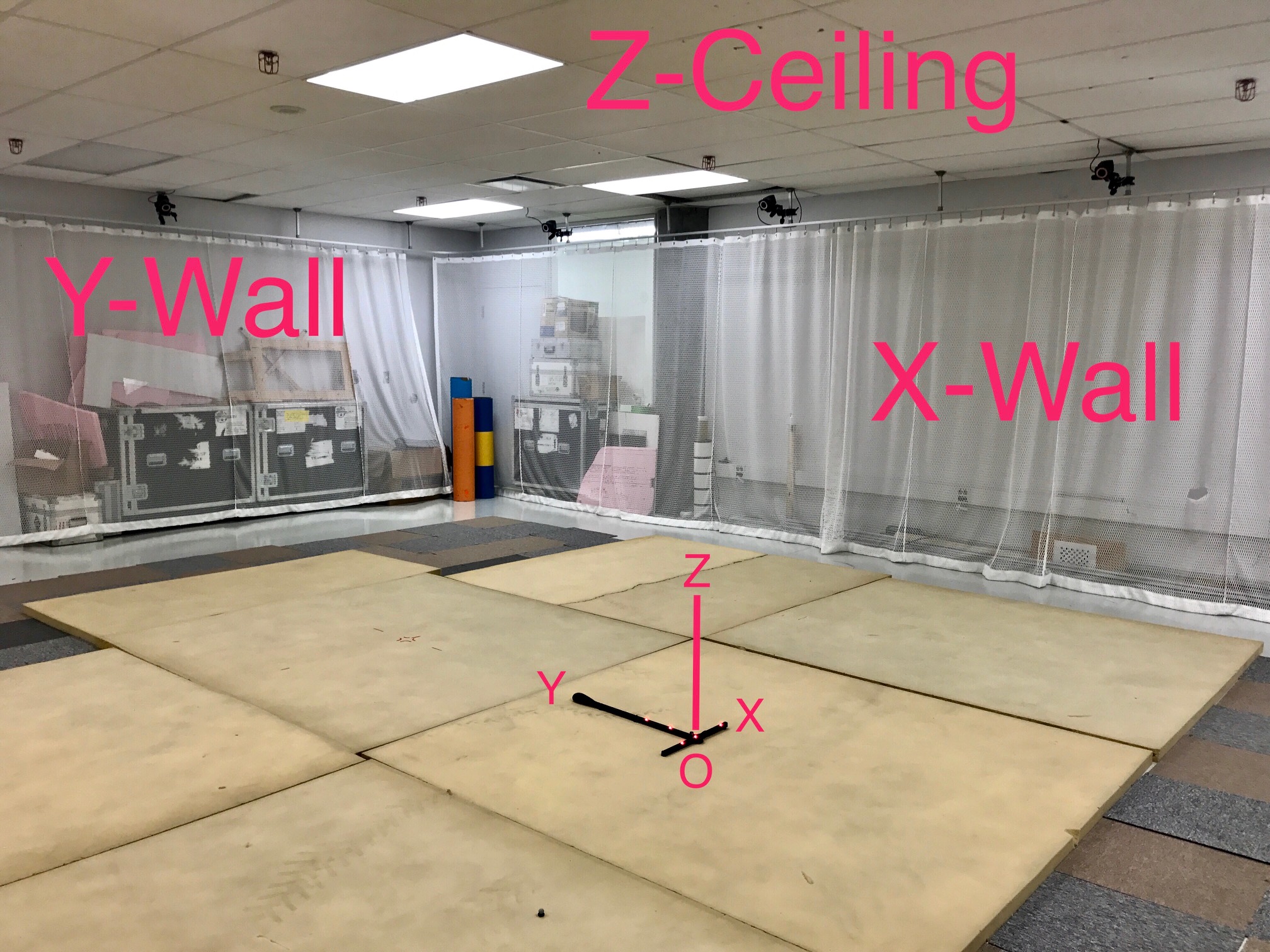 N.B. Our lab has adopted the convention that the longest wall is facing the X axis and the shortest the Y axis. The ceiling is facing the Z axis. If you change the orientation of the origin, always make sure that you replace it this way before quitting.
Navigate to and select:
CALIBRATE > SET VOLUME ORIGIN > STARTYou should see in the 3D Perspective camera view that the program has recognized the Active Wand. Cick on _SET ORIGIN. _The orientation of the flight area should now be good.
Go back to the first step and this time select:
SYSTEM > 12_Cam_Config_250HzYou are now done with the calibration procedure and the Vicon system is now ready to be used :D